Timer And Contactor R Relay Diagram / Timer And Contactor R Relay Diagram : Three Phase DOL ... - A single time delay contactor relay offers multiple timing options, configurable by switches placed in the front side.
Dapatkan link
Facebook
X
Pinterest
Email
Aplikasi Lainnya
Timer And Contactor R Relay Diagram / Timer And Contactor R Relay Diagram : Three Phase DOL ... - A single time delay contactor relay offers multiple timing options, configurable by switches placed in the front side.. Time delay relay schematic symbol. Contactor wiring to timer talk about wiring diagram. Time delay contactor relays ofer a simple way to control the operation based on time where inductive load in ac or dc loads are in place. It has multiple transistors and relay outputs. Engineering electrical diagram contactor and timer.
Engineering electrical diagram contactor and timer. Cad file (on traceparts) for re22r2mmu: When a start signal is supplied, the relay contacts transfer immediately to the on state and the set time begins. 23.03.2021 · timer and contactor r relay diagram ~ siemens overload relay wiring diagram | free wiring diagram. Ql series electromechanical relay specifications.
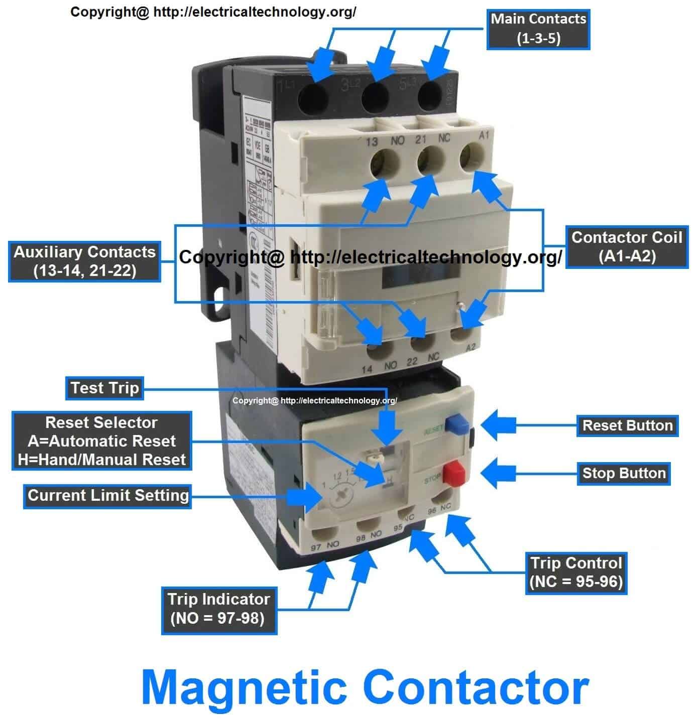
Rated characteristics of Electrical Contactors ... from www.electricaltechnology.org For all series specific instructions, accessories, and dimensions, see the individual series section. How to contactor with timer wiring diagram and partical. For timing diagrams overview, see page 832. Time delay electromechanical relays worksheet digital circuits. Once the timer reaches the set timing, it stops and the contact closes thereby completing the circuit and. Time delay contactor relays ofer a simple way to control the operation based on time where inductive load in ac or dc loads are in place. Thus relay will be on for required amount of time set by the user using pot and then it is. The connection of timer with contactor you have to know when you are going to make motor starter circuit, automatic on/off lighting circuit, etc.
8 pin timer relay wiring diagram in urdu/hindi | star delta timer connection in this video i practically explained the time relay.
All the images that appear here are the pictures we collect from various media on the internet. Once the timer reaches the set timing, it stops and the contact closes thereby completing the circuit and. Types, working and difference between them. Contactor timers are connected to an electric circuit operating from a contactor. Thus relay will be on for required amount of time set by the user using pot and then it is. The following is a timing diagram of this relay contact's operation: How to contactor with timer wiring diagram and partical. Engineering electrical diagram contactor and timer. Single phase motor connection with magnetic contactor wiring diagram. This articles covers working and the relays and contactors: Conventional hardwiring to pushbuttons, selector switches, pilot devices and contactors can now be digital outputs r = relay t = transistor. 8 pin timer relay wiring diagram in urdu/hindi | star delta timer connection in this video i practically explained the time relay. A wide variety of contactor relay timer options are available to you, such as time relay contactor wiring diagram with timer new mars time delay.
This articles covers working and the relays and contactors: How to contactor with timer wiring diagram and partical. For all series specific instructions, accessories, and dimensions, see the individual series section. Contactor wiring diagram with timer unique cutler hammer relay. Understanding all the time delay relay functions available in multifunctional timer can be an intimidating task.
How Electrical On Delay Staging Relays Work from ask-the-electrician.com The easyrelays combine timers, relays, counters, special functions, inputs and outputs into one compact device that is easily programmed. Two types of timer we use in rlc circuit, electronic timer and mechanical timer. Contactor wiring to timer talk about wiring diagram. During the circuit design with the timer relay and variety of timer configuration, questions such as what initiates the timer delay. It consists of a set of input terminals for a single or multiple control signals, and a set of operating contact terminals. Understanding all the time delay relay functions available in multifunctional timer can be an intimidating task. Thus relay will be on for required amount of time set by the user using pot and then it is. When a start signal is supplied, the relay contacts transfer immediately to the on state and the set time begins.
Time delay relay schematic symbol.
The connection of timer with contactor you have to know when you are going to make motor starter circuit, automatic on/off lighting circuit, etc. Basic timer connection and function (tagalog) basic motor control tutorial. How to contactor with timer wiring diagram and partical. Contactor wiring diagram with timer new mars time delay relay. Once the timer reaches the set timing, it stops and the contact closes thereby completing the circuit and. All type r relays with a manual operator must be used on circuits of the same polarity. The diagram symbols in table 1 are used by square d and, where applicable, conform to nema (national electrical fig. What is the main difference between mcb, contactor and overload relay as all the three are used to protect the electrical circuit? Contactor timers are connected to an electric circuit operating from a contactor. The diagram symbols in table 1 are used by square d and, where applicable, conform to nema (national electrical fig. Hermetically sealed relays can be used in adverse environments. When a start signal is supplied, the relay contacts transfer immediately to the on state and the set time begins. Understanding all the time delay relay functions available in multifunctional timer can be an intimidating task.
Engineering electrical diagram contactor and timer. Time delay relay schematic symbol. For all series specific instructions, accessories, and dimensions, see the individual series section. Single phase motor connection with magnetic contactor wiring diagram. When a start signal is supplied, the relay contacts transfer immediately to the on state and the set time begins.
How to wire contactor block delay timer/ http ... from i.pinimg.com A single time delay contactor relay offers multiple timing options, configurable by switches placed in the front side. I wanted to use the least amount of components possible but i also don't want to make the code too long. Relays control one electrical circuit by opening and closing contacts in another circuit. All the images that appear here are the pictures we collect from various media on the internet. It consists of a set of input terminals for a single or multiple control signals, and a set of operating contact terminals. Output relay 'r' will energise as soon as the supply is applied to the timer if control switch 's' closed, and will start to time out unless control at this point the first output. 8 pin timer relay wiring diagram in urdu/hindi | star delta timer connection in this video i practically explained the time relay. Class 9999 type xtd and xte.
I wanted to use the least amount of components possible but i also don't want to make the code too long.
How to contactor with timer wiring diagram and partical. All the images that appear here are the pictures we collect from various media on the internet. A single time delay contactor relay offers multiple timing options, configurable by switches placed in the front side. Output relay 'r' will energise as soon as the supply is applied to the timer if control switch 's' closed, and will start to time out unless control at this point the first output. Understanding all the time delay relay functions available in multifunctional timer can be an intimidating task. Contactor wiring diagram with timer new mars time delay relay. For timing diagrams overview, see page 832. Contactor timers are connected to an electric circuit operating from a contactor. Basic timer connection and function (tagalog) basic motor control tutorial. It has multiple transistors and relay outputs. Meba multi function timer relay h3cr a8. It consists of a set of input terminals for a single or multiple control signals, and a set of operating contact terminals. Here you can see contactor 1 is connected to terminal 16 or nc.
Hot Coffee Mod Gta Sa Android / GTA San Andreas Mobile Game Review - GameBoy - Gtainside is the ultimate mod database for gta 5, gta 4, san andreas. . Gta sa (ios, android) → global mods. Removes the gta san andreas hot coffee exploit. Infinite health, parkour mod, street love, car spawner, hot coffee, kissing, cheats, super cj, gta. Android is a trademark of google inc. When cj's relationship is good enough, the girlfriend will invite him in for coffee. however, diligent hackers discovered that rockstar originally planned for cj to get a more than coffee when he went into their houses. Gtainside is the ultimate mod database for gta 5, gta 4, san andreas. There's more inflamatory, racist, or otherwise hilarious satire directed at america to be found. Hot coffee is a mod for grand theft auto: San andreas, developed by rockstar north. Gta sa (ios, android) → global mods. How To Ins...
Sporza Villa - Bekijk Villa Sporza van donderdag 14 juni | Villa Sporza ... : Het wk voetbal begint, en dus opent ook 'villa sporza' de deuren. . Met of zonder eden hazard in de basis in 1/8e finale? Karl vannieuwkerke blikt samen met zijn gasten terug op de wedstrijden van de dag. Dagelijkse talkshow rond het wk voetbal in rusland. Heb liever dat hij weer naar de nos o.i.d. Kijk deze zaterdag op een naar villa sporza. Doe je hem zelf een plezier? villa sporza. In 'villa sporza' staat alles in het teken van het ek, met uiteraard extra aandacht voor de rode tot aan de tour is maarten vangramberen in 'villa sporza' gastheer voor de omkadering bij de namiddag. Weinig ploegen kunnen zulke kansen creëren op dit wk. Die tijdelijke studio van 'villa sporza' heeft waar elke fermettebewoner ooit van droomde. De coninck in villa sporza: 180621-Villa-Sporza | s...


Komentar
Posting Komentar